



Desain Tata Letak Pin Posisi Cetakan: Kontrol Jarak dan Batasan
A reliable mold positioning pin layout controls the required movement with the fewest necessary locating constraints. For a mold plate or removable insert, that usually means establishing the main in-plane position with a primary locator and preventing rotation with a secondary locator that does not create unnecessary binding.
Pin spacing should be wide enough to reduce angular sensitivity, but it cannot be chosen from spacing alone. Plate strength, datum fungsional, saluran pendingin, screws, komponen ejector, pergerakan termal, machining access, and future pin removal all affect the final layout.
This guide focuses on fixed locating or dowel features used to position mold plates, sisipan, and tooling components. For broader guidance on moving mold-half alignment, operating fit, memakai, dan pemeliharaan, lihat pin cetakan dan bushing (disimpulkan).
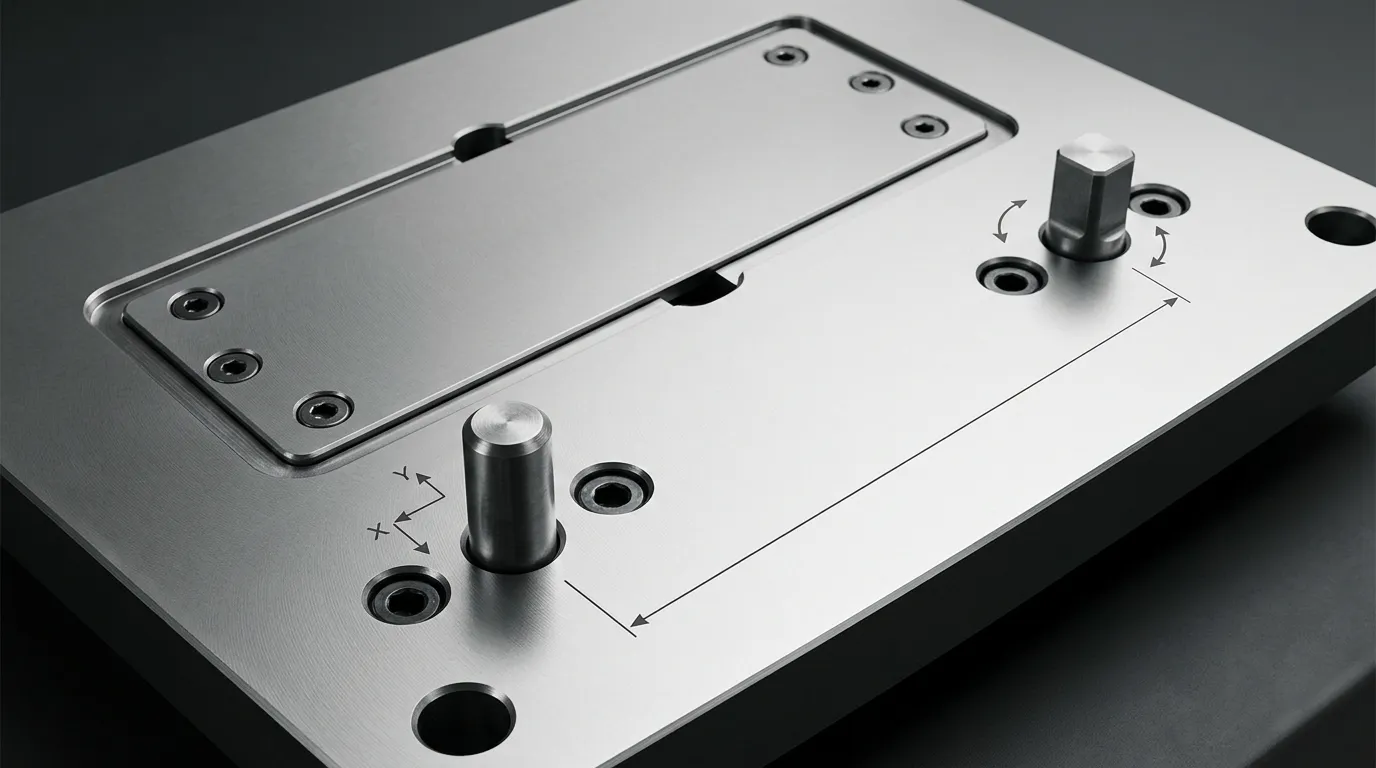
Apa yang harus dikendalikan oleh tata letak pin pemosisian
Before placing any pin, define what the component is allowed to do.
A plate or insert resting on a mating surface can still move in three ways within that plane:
- translate along the X direction;
- translate along the Y direction;
- rotate around an axis perpendicular to the plate.
The positioning-pin layout must control those three in-plane movements. The mating face establishes the seating plane, while screws or clamps retain the component against that face.
This distinction matters because not every mold component performs the same task.
Separate Locating, Guiding, Fastening, and Load Control
| Fitur | Peran utama | Apa yang tidak boleh diasumsikan untuk dilakukan |
|---|---|---|
| Pemosisian atau pin dowel | Tetapkan pelat yang dapat diulang atau lokasi sisipan | Ganti semua clamp atau bawa setiap beban operasi |
| Pin panduan dan bushing | Pandu bagian cetakan selama pembukaan dan penutupan | Sediakan satu-satunya lokasi tetap untuk sisipan yang dapat dilepas |
| Sekrup pemasangan | Clamp atau pertahankan komponen | Establish precise, repeatable position by itself |
| Kunci samping atau interlock | Melengkapi pemosisian akhir atau menahan kondisi lateral tertentu | Ganti skema penempatan pelat yang didefinisikan dengan benar di setiap aplikasi |
A fixed dowel location and a moving guide system may both contribute to alignment, Tapi mereka menyelesaikan masalah yang berbeda. Detailed guide-system selection, memakai, and maintenance belong with pin panduan cetakan, not in the positioning-pin layout itself.
Positioning pins should also not be treated automatically as the main load-carrying elements. Where the mold experiences significant lateral force, final parting-line location or load resistance may require side locks, taper locks, penguncian, bahu, or other structural features.
Kontrol tiga gerakan dalam bidang tanpa menambahkan batasan yang berlebihan
The layout should constrain only the movements that must be controlled.
A common approach is:
- A primary round locator controls translation in X and Y.
- A secondary locator prevents rotation.
- The mating surface controls seating.
- Screws provide clamping or retention.
Adding more tightly fitted pins does not necessarily increase accuracy. If several locators attempt to control the same movement, small differences in hole position, pin size, suhu, or machining error can make the component difficult to assemble.
This condition is called overconstraint. Its effects may include binding, forced assembly, internal stress, damaged locating holes, or inconsistent seating.
Pilih Skema Penempatan Primer dan Sekunder
The primary and secondary locators should be selected according to the movement each feature must control.
The correct arrangement depends on component geometry, manufacturing tolerances, suhu operasi, assembly frequency, and the distance between locating points. No one arrangement is best for every mold.
Gunakan pin bulat utama untuk menetapkan lokasi utama
The primary round pin normally establishes the main in-plane position. Its cylindrical contact controls movement in two directions.
Place this locator relative to the functional mold feature rather than choosing a location only because it is near a convenient plate corner. Misalnya, if the position of a cavity insert relative to another machined feature is critical, the primary locator should belong to the same functional datum strategy.
The primary location should also be accessible for:
- drilling and reaming;
- inspeksi dimensi;
- perakitan;
- extraction or replacement;
- repair if the hole becomes worn or damaged.
The physical centre of the plate is not automatically the best primary location. Functional control matters more than visual symmetry.
Lepaskan arah sekunder ketika dua lokasi bulat yang ketat akan mengikat
A second locator is required to prevent the component from rotating around the primary pin. The problem is that a second tightly fitted round pin also tries to control X and Y.
If the centre distance between the two holes differs slightly from the centre distance between the two pins, the assembly can bind even when each individual diameter is within tolerance.
A diamond pin, relieved pin, or pin-and-slot arrangement avoids this redundant constraint. The secondary locator contacts the mating feature in the direction required to prevent rotation while allowing clearance in the perpendicular direction.
The relief must be oriented correctly. If the relieved direction is turned the wrong way, the secondary locator may fail to control rotation or may still create the centre-distance conflict it was intended to solve.
ASME Y14.5 provides the formal framework for communicating datum relationships and controlled degrees of freedom. Bimbingan teknis dari FARO di lokasi pin berlian also illustrates how directional relief reduces redundant constraint.
| Pengaturan lokasi | Perilaku kendala | Keuntungan utama | Batasan utama |
| Dua pin bundar yang terpasang rapat | Kedua pin mencoba mengontrol dua arah | Geometri sederhana | Sensitif terhadap kesalahan jarak tengah dan variasi termal |
| Pin bulat ditambah berlian atau pin yang lega | Primary controls X/Y; secondary controls rotation | Mengurangi kendala berlebih | Orientasi relief harus didefinisikan dengan benar |
| Pin bulat ditambah lubang sekunder berlubang | Slot memungkinkan pergerakan dalam satu arah | Mudah dipahami dan diperiksa | Pembuatan slot dan geometri kontak harus dikontrol |
| Pin bulat plus pencari lokasi mengambang | Fitur sekunder mengkompensasi variasi yang lebih besar | Berguna jika jarak tengah berubah secara signifikan | Persyaratan komponen dan inspeksi yang lebih kompleks |
A floating locator may be useful where centre-distance change is larger than a simple relieved pin can accommodate, such as in long assemblies or components exposed to meaningful temperature differences. It should be selected from verified component data rather than treated as a default solution.
Ketika dua pin bundar mungkin masih sesuai
Two round pins are not automatically wrong.
They may work when:
- the pin centre distance is tightly controlled;
- the mating-hole centre distance is controlled from the same datum system;
- one mating condition includes sufficient clearance;
- temperature variation is limited or accounted for;
- the worst-case tolerance condition has been checked;
- the assembly can be installed without forcing.
The decision must be based on the complete tolerance relationship, not nominal dimensions alone.
Atur Jarak Pin yang Berguna dan Cegah Perakitan Terbalik
Positioning pins should generally have the longest practical locator baseline.
The locator baseline is the effective distance between the two locating points that resists rotation. Increasing that distance reduces the angular effect of the same amount of hole-position error.
This does not mean the pins should always be placed at the farthest possible corners. Wider spacing is useful only when the resulting locations remain structurally sound, dapat diproduksi, dapat diakses, and clear of other mold systems.
Gunakan Baseline Pencari Lokasi Praktis Terpanjang
Consider two locating points separated by a short distance. If the secondary hole shifts slightly, the component rotates around the primary locator.
Now consider the same hole-position shift with the locating points farther apart. The resulting angular change is smaller because the error acts across a longer baseline.
The effect becomes more noticeable at functional features located far from the locators. A small angular error near the pins may produce a much larger positional shift at the opposite end of a long insert or plate.
Panduan penempatan dowel praktis dari MISUMI TechCentral follows the same principle: greater separation between locating points reduces sensitivity to equivalent location error. The exact spacing still depends on the mold design.
Seimbangkan jarak yang lebih luas terhadap kendala pelat dan sistem
Useful separation must be balanced against other requirements.
Check whether a wider pin pattern creates any of the following problems:
- insufficient material between the locating hole and a plate edge;
- intersection with a cooling channel or cooling plug;
- conflict with mounting screws or counterbores;
- interference with ejector pins, pin pengembalian, or ejector-plate features;
- conflict with support pillars or load-bearing areas;
- entry into hot-runner manifold, heater, nozzle, or wiring zones;
- blocked sensor or connector access;
- difficult drilling, reaming, or inspection;
- limited extraction access;
- excessive thermal centre-distance change.
A locator placed near a plate edge may improve the angular baseline, but the remaining plate ligament must still withstand manufacturing, perakitan, dan kondisi operasional. There is no universal edge distance that is safe for every material, ketebalan pelat, diameter pin, or load case.
Buat pola asimetris untuk perakitan anti kesalahan
A symmetric two-pin pattern may allow a plate or insert to be rotated or reversed and still appear to fit.
An asymmetric pattern makes the intended orientation unique. This can be achieved by:
- offsetting one locator from the centreline;
- using different distances from adjacent edges;
- staggering the primary and secondary locations;
- combining different locator forms;
- making one orientation physically impossible.
The purpose is not visual variety. It is mistake-proofing.
The pattern should remain unambiguous after the mold has been disassembled for maintenance. A technician should not need to rely on memory or a temporary marking to identify the correct orientation.
Periksa tata letak terhadap geometri cetakan dan akses servis
After choosing the locating scheme and approximate spacing, review the complete mold assembly in CAD.
A locating hole is not an isolated feature. Its drilling path, lubang belakang, mating hole, extraction path, and surrounding plate material may pass through several stacked components.
Buat peta rintangan sistem cetakan sebelum mengebor lubang pencari lokasi apa pun
Show all relevant systems in the same review model:
- saluran pendingin, plugs, perlengkapan, and cross-drillings;
- mounting screws and counterbores;
- ejector-pin and return-pin holes;
- ejector-plate movement envelopes;
- pilar-pilar penyangga;
- hot-runner manifolds, nozzles, heaters, and wiring;
- slide and lifter mechanisms;
- sensors and connectors;
- lifting holes and handling features;
- insert pockets and neighbouring replaceable components.
Check hidden paths, not only visible bodies. A proposed locating hole may clear a component in one plate but intersect a cooling drilling or screw counterbore deeper in the stack.
Movement also matters. A hole that is clear in the closed CAD position may conflict with an ejector, slide, or other moving feature during operation or maintenance.
Preserve Plate Strength and Access for Assembly, Inspeksi, and Removal
A workable layout must remain serviceable throughout the mold’s life.
Confirm that:
- the hole can be drilled and reamed from the intended direction;
- inspection equipment can access the locating surfaces or datums;
- the pin has an extraction method when replacement may be required;
- plate separation does not trap the pin unexpectedly;
- the insert can be removed without damaging the locating surfaces;
- the selected engagement length does not obstruct neighbouring features;
- future hole repair, bushing, or oversize rework remains possible.
A precise location that cannot be machined, measured, or repaired is not a complete design.
Define Functional Datums, Position Tolerances, and Thermal Relief
The locating pattern must be communicated through a drawing or controlled digital model that reflects the intended function.
Pin diameter alone is not enough. The drawing must also control where the holes are located relative to the component’s functional datums.
Dimensi pola pencari lokasi dari datum fungsional
Select datums according to how the mold plate or insert works in the assembly.
A practical datum strategy should identify:
- the seating surface;
- the primary functional reference;
- the direction that establishes orientation;
- the relationship between the primary and secondary locating holes;
- the critical molded, machined, or mating feature controlled by the layout.
Avoid locating both holes only from arbitrary outside edges unless those edges genuinely control mold function.
Positional tolerancing can communicate the permissible location of the hole axes relative to the datum reference frame. The inspection method should reproduce the same datum setup used by the design.
The article does not prescribe one tolerance value because the correct value depends on the required repeatability, component size, manufacturing process, kemampuan inspeksi, and mating clearances.
Validasi Kondisi Kecocokan dan Suhu Terburuk
Check the assembly at the most restrictive combination of permissible dimensions.
The analysis may need to include:
- maximum pin diameter;
- minimum mating-hole diameter;
- position error of the installed pins;
- position error of the mating holes;
- form and perpendicularity variation;
- temperature-related change in pin or hole centre distance;
- orientation and available relief at the secondary locator.
Itu Sistem batas dan kesesuaian ISO 286 provides standard terminology and tolerance classes for mating holes and shafts. Parallel dowel-pin categories may also be specified using standards such as ISO 8734 atau ISO 2338 jika berlaku.
These standards provide a framework. They do not select the correct fit for a particular mold automatically.
Thermal movement deserves attention when:
- the locator baseline is long;
- the mating components use different materials;
- assembly and operating temperatures differ;
- one component heats more than the other;
- the mold operates across a wide temperature range.
A relieved secondary direction can accommodate permitted centre-distance change while maintaining rotational control. The relief must still leave enough contact in the controlled direction to meet the location requirement.
Tinjau kegagalan tata letak umum sebelum melepaskan gambar
Most positioning-pin problems can be traced to a small set of layout mistakes.
| Kesalahan tata letak | Kemungkinan konsekuensi | Arah korektif |
| Terlalu banyak pin penempatan yang ketat | Pengikatan atau perakitan paksa | Hapus batasan yang berlebihan atau perkenalkan pelepasan arah |
| Dua pin bundar dengan jarak tengah yang tidak kompatibel | Perakitan yang sulit atau lubang rusak | Review fit, position tolerance, and secondary-locator design |
| Pencari lokasi ditempatkan terlalu berdekatan | Peningkatan sensitivitas sudut | Tingkatkan baseline yang berguna jika praktis |
| Pola simetris | Pelat terbalik atau rakitan sisipan | Stagger atau offset satu locator |
| Pin terletak dari tepi pelat sewenang-wenang | Ketidaksejajaran fitur fungsional | Dimensi dari datum fungsional |
| Pin berlian tidak berorientasi dengan benar | Kehilangan kontrol rotasi atau pengikatan berkelanjutan | Tentukan arah yang dikontrol dan dibebaskan pada gambar |
| Lubang terlalu dekat dengan tepi atau saku | Ligamen lempeng lemah atau risiko retak | Memposisikan ulang atau memverifikasi bagian yang tersisa secara analitis |
| Tabrakan tersembunyi dengan fitur pendinginan atau ejeksi | Pengerjaan ulang pemesinan atau kerusakan sistem | Jalankan tinjauan interferensi CAD mendalam penuh |
| Tidak ada akses ekstraksi | Perawatan yang sulit atau penghapusan yang merusak | Menambahkan jalur penghapusan atau fitur ekstraksi |
| Pemeriksaan toleransi nominal saja | Kegagalan perakitan pada batas toleransi | Memvalidasi kondisi terburuk |
| Pin atau sekrup pemandu diperlakukan sebagai pencari lokasi tetap akhir | Posisi sisipan atau pelat yang tidak konsisten | Tetapkan setiap fitur fungsi yang ditentukan secara terpisah |
| Aturan spasi yang disalin | Desain yang belum diverifikasi | Base placement on geometry, pemuatan, toleransi, and access |
Daftar Periksa Tata Letak Pra-Rilis
Before releasing the mold positioning pin layout design, konfirmasi hal berikut:
- The functional seating surface and datums are defined.
- The required X, Y, and rotational constraints are identified.
- The primary locator establishes the intended main position.
- The secondary locator controls rotation in the correct direction.
- Redundant directional constraint has been removed where necessary.
- The locator baseline is as long as practical.
- The pattern cannot be assembled in the wrong orientation.
- Plate-edge and pocket ligaments remain acceptable.
- Pendinginan, pengusiran, fastening, dukungan, hot-runner, sensor, and wiring conflicts have been checked.
- Pengeboran, reaming, inspeksi, perakitan, and extraction access are available.
- Worst-case pin size, ukuran lubang, posisi, and temperature have been reviewed.
- Drawing notes identify locator function, tanggal, controlled direction, fits, and applicable standards.
- Screws, pin pemandu, and interlocks have clearly separated roles.
Siapkan Spesifikasi Pin dan Handoff Pemasok
Once the layout has been validated, convert the design into a complete component and hole specification.
Do not send only a nominal pin diameter and overall length. The supplier needs enough information to understand how the component functions in the locating system.
Sertakan persyaratan fungsional dan inspeksi pada gambar
Tergantung pada desainnya, specify:
- whether the component is the primary or secondary locator;
- whether it is round, diamond, lega, meruncing, berbahu, or otherwise modified;
- the controlled and relieved directions;
- nominal diameters and lengths;
- mounting and locating portions;
- lead-in geometry;
- removal or extraction features;
- applicable material and heat-treatment requirements;
- surface-finish or treatment requirements where necessary;
- datum references and positional controls;
- mating-hole requirements;
- inspection characteristics and required records;
- applicable ISO or drawing standards;
- drawing revision and quantity.
The mounting fit and the locating fit should be treated as separate functional decisions. One portion may retain the pin in a plate, while another portion locates the mating component. The exact fit must be validated from the application, tolerance analysis, and qualified manufacturing data.
Tentukan Antara Komponen Penempatan Standar dan Kustom
A standard component is usually preferable when its geometry, toleransi, material, metode penghapusan, and available lengths meet the design.
Custom geometry may be justified when the layout requires:
- a special relieved direction;
- a nonstandard shoulder;
- a tapered locating portion;
- an extraction thread;
- an unusual engagement length;
- restricted installation access;
- a special interface between mounting and locating diameters.
Sunshine lists straight, meruncing, and drawing-based custom options on its Halaman Produk Dowel-Pin. Its website also presents customization of dimensions, toleransi, material, dan finishing permukaan. These are listed offerings rather than proof that every drawing or tolerance can be produced, so project-specific capability should be confirmed before release.
For broader guidance on deciding between catalogue components and customized parts, lihat Bagian standar cetakan.
After the locator roles, dimensi, tanggal, toleransi, persyaratan material, kondisi operasi, and inspection needs are defined, the drawing can be reviewed with a component supplier. Sunshine’s Halaman kontak provides a route for discussing standard or custom locating-pin requirements without replacing the mold designer’s own fit, kekuatan, and tolerance validation.
Bagikan:


Ditulis oleh Sunshine
di Sunshine, Kami adalah produsen dan pemasok profesional komponen cetakan presisi, menawarkan berbagai produk untuk aplikasi stamping dan cetakan injeksi. Fokus utama kami adalah mencetak cetakan, pin dan lengan ejector, serta tiang panduan dan bushing. Dengan pemesinan CNC canggih, kontrol kualitas ketat, dan kemampuan produksi yang kuat, kami memastikan keandalan, suku cadang presisi tinggi, bersama dengan komponen standar yang tersedia untuk pasokan global yang cepat dan efisien.
BERITA
DAPATKAN LAYANAN
Dengan suku cadang berkualitas untuk memenuhi setiap anggaran dan staf ramah yang terlatih untuk membuat kunjungan Anda menjadi informatif dan tanpa repot.
